A question came up along IRC regarding how to PWM a 3-pin Microcomputer buff with an Arduino using analogWrite(). Controlling the fan was apparently straightforward. The problem was that the Granville Stanley Hall issue sensor, Beaver State TACH sign, was incredibly noisy. The noise made IT impossible to measure the fan's rotation. Working through the question, I base three issues to tackle:
- You need to use a PNP transistor
- Filtrate capacitors help
- Create a non-blocking RPM measurement (with millis())
This post addresses all three issues regarding how to PWM a 3-pin PC fan with an Arduino.
1. You need a PNP Junction transistor
Most tutorials show an NPN transistor dynamic a motor as a low-side switch. However, the problem with this approach is that you are switch the ground (GND) path. This method acting doesn't cater a deliver path when the FAN is turned off. Regarding the devotee's mental process, IT will round off and on as you expect. However, the lack of ground path means the switching fire make magnetic force preventative (EMI).
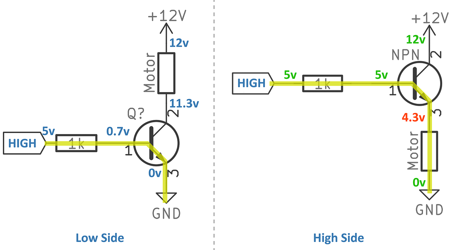
Figure 1: Don't dress this!
The proper way to power a fan is with a high-side switch. This circuit type switches the high voltage along and off, instead of ground. Only you can't use a NPN. Figure 1 shows the trouble. When configured as a high-side switch the voltage from across VEmbody remains 0.7 volts. Which means if there is 5 volts at the foundation, you only get 4.3 volts at the collector. You were probably expecting it to be 11.3 volts, weren't you? Well, that's not how a NPN BJT whole shebang.
Or else, we can use a PNP transistor for the high-go with electrical switch. This circuit does present a trouble when using 5 volts on the base and 12 V on the emitter.
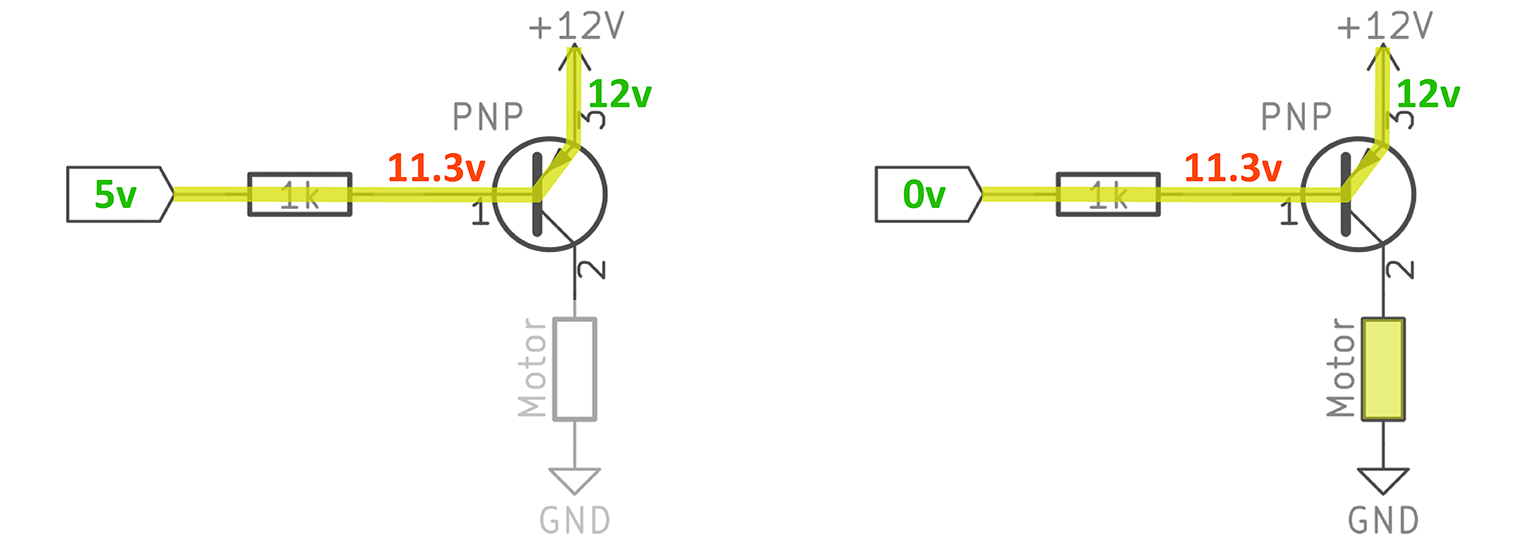
Count on 2: Oops. 12V rail with a 5V control.
So the problem is that when the I/O pin is HIGH or Low, there isn't enough voltage to turn of events off the electronic transistor. And you make over an ungainly potential divider betwixt the I/O pin and the base of the transistor. If you looked at the collector (shown as immobilise 2 in this diagram) on an oscilloscope, you'd see it stay a steady DC voltage. Not rattling useful is it?
To solve the problem of how to use a PNP transistor with an Arduino, you motivation to add an NPN number one wood. It seems kind of silly doesn't it? Well, doing things right ISN't always sluttish. Or something to that effect.
NPN-PNP Driver Good example
If we add a NPN transistor before the PNP, IT bottom be accustomed switch the heights-voltage supply on and murder. This driver would allow the PNP's base to see a wide voltage range. The NPN arse pull the PNP's base, with its current restrictive resistance, to 12 volts. This mode bequeath prevent 0.7 volts from dropping crosswise the Base-Emitter semiconductor diode keeping the transistor Soured. When the NPN drops to ground, so VBE becomes hands-on, and the transistor turns on.
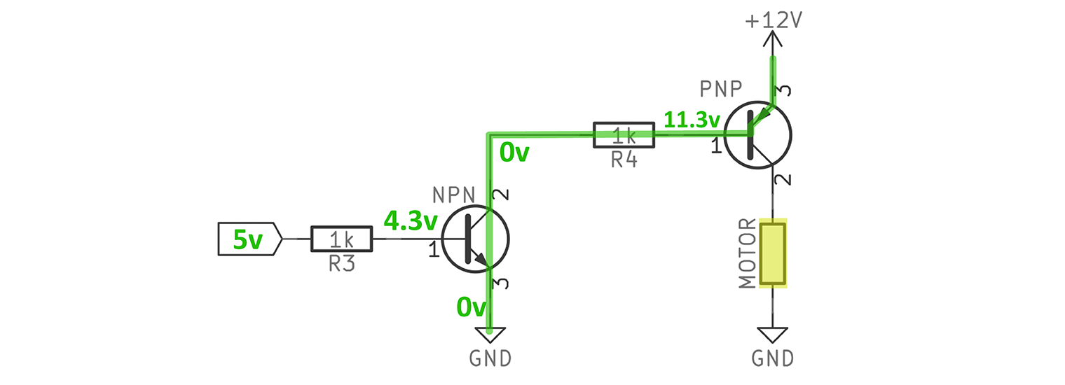
Figure 3: I/O Pin is HIGH, Motor is ON
In Figure 3, I'm showing what happens with the NPN-PNP driver when the Arduino drives 5 volts. It turns along the NPN, which affined the PNP's base resistor to ground. This path allows 0.7 volts to drop across the PNP's Emitter to Bag junction. The transistor turns Connected and the motor spins.
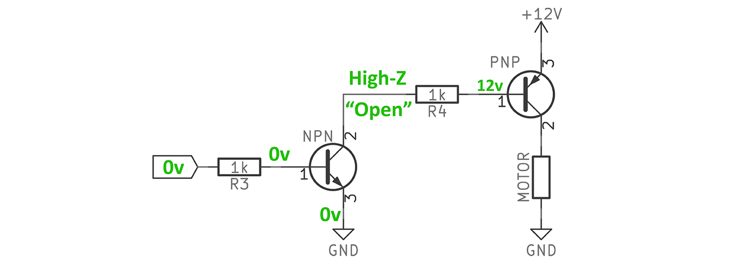
Figure 4: I/O Flag is Low-growing, Motor is OFF.
Now, when the I/O PIN number goes LOW, something more gripping happens. The NPN turns into an capable because it's Al-Qaeda-Emitter junction is off. So that leaves the PNP's base resistor uncommitted. Thusly that means if there is 12 volts on the Emitter, that is the anode of the junction diode. Since current bathroom't flow through the NPN, the cathode of the articulation diode is in effect floating, meaning it will show the 12V wired to its anode. So the VBE becomes: 12v – 12v = 0v. This relationship keeps the PNP, and the motor, OFF.
2. Trickle Capacitors Service when you PWM a 3-PIN PC fan with an Arduino
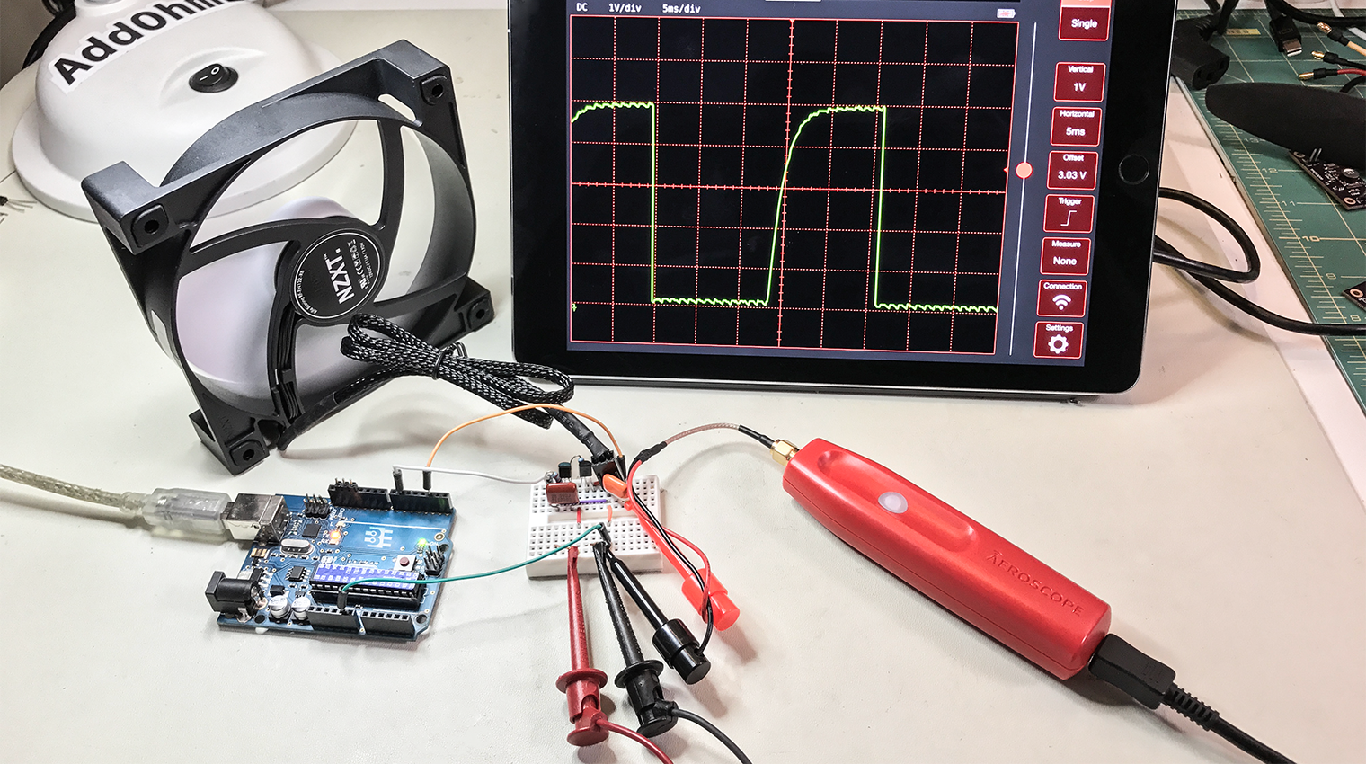
Once this was totally setup, I connected my ambit and saw the following:
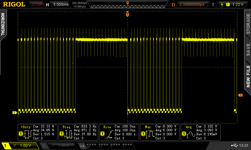
Figure 5: Noisy RPM Indicate with PWM
All of the noise spikes shown are finding their mode into the I/O peg. It falsely triggered the interrupt, messing ahead an Revolutions per minute measurement. So what's active on here? Where are those spikes approaching from? The spikes are EMI from high frequencies in the PWM signal.
But wait, the PWM signal from the Arduino is exclusively around 600 Hz. That isn't very fast. The 600 Cps isn't our issue. Instead, IT is how fast the PWM signal switches from OFF to ON.
EMI comes from the Edge
The edge rate from the Arduino I/O pin, and the NPN related to to IT, transitions from Downcast to Soprano implausibly fast. There is a great deal of what we call "high-frequency content" therein abut. That's what is making its direction onto the hall-set up detector. All of those little spikes are EMI noise. A simpleton root is to moderato down the edge to the OFF to ON transition. Connecting a condenser from the NPN's collector to ground slows down the edge into the base of the PNP. The current limiting resistance (R1) and capacitor (C2) form an RC network, which reduces a lot of the noise.
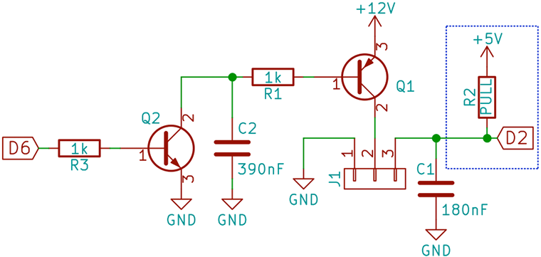
Work out 6: Final Arduino PWM PC Fan Circuit
Pick the PWM Trickle Capacitor
Normally you could do a bunch of math to figure out an ideal resistor-capacitor combination. In my case, I just abutting a 390nF Ceramic capacitor for C2 and all was good. I did look at using a 470nF and 1uF electrolytic capacitor. However, those had enough electrical capacity to even out the voltage creating a constant ~10V, preventing any switching. Additionally, their ESR causes substantial "shelves" to appear on the edge. Stick to ceramics operating theater film capacitors for this type of filtering.
Depending on your circuit, you whitethorn need to take on with that value. Basically, make it big sufficiency to reduce the noise spikes, but low enough that the NPN put up still replacement the PNP off.
You'atomic number 75 probably going to want a compass for this measurement.
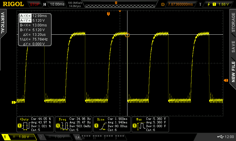
Figure 7: Multiple Cycles from Hall Effect
The hall sensor is still a flake noisy, specially on the rising sharpness. The falling edge is jolly clean. So even though this signal is sporty Elated, I decided to measure the falling butt on. I did find adding some additional capacitor along the detector signal helps clean information technology up a bit more than. You could too consider performin around with an external draw out-up resistor to for a look-alike RC the likes of filter.
With my PWM signal energetic working well and the hall sensor signal cleaned up, IT was time to measure RPMs on the Arduino.
3. RPM Measurement with millis()
I created a arrow-shaped serial interface (single character commands) to adjust the PWM speeds. There is a one-s interval utilized to video display current RPM. The interrupt is used only for counting pulses from the Charles Martin Hall effect sensor. Still, I don't think even that is necessary. (Maybe something to tackle in another tutorial.) RPM calculation is pretty radical, but seems to work. My fan is rated for 1200 RPM and I'm measuring 1250ish. The slowest I can seem to run this fan is 600 RPM.
As accustomed, no delays means you can well incorporate this code into other Arduino sketches.
unsigned long previousRPMMillis; unsigned long previousMillis; float RPM; unsigned long interval = 1000; byte pwmValue = 125; byte pwmInterval = 5; const byte pwmMax = 255; const byte pwmMin = 0; const int reedPin = 2; const int fanPin = 6; volatile unsigned long pulses=0; unsigned long lastRPMmillis = 0; void countPulse() { // just count each pulse we see // ISRs should be short, not like // these comments, which are extended. pulses++; } nullity frame-up() { Serial.lead off(9600); pinMode(reedPin,INPUT_PULLUP); attachInterrupt(digitalPinToInterrupt(reedPin), countPulse, FALLING); pinMode(fanPin, Turnout); // probably PWM } unsigned long calculateRPM() { unsigned long RPM; noInterrupts(); float elapsedMS = (millis() - lastRPMmillis)/1000.0; unsigned long revolutions = pulses/2; float revPerMS = revolutions / elapsedMS; Revolutions per minute = revPerMS * 60.0; lastRPMmillis = millis(); pulses=0; interrupts(); /*Sequent.impress(F("elpasedMS = ")); Serial.println(elapsedMS); Serial.impress(F("revolutions = ")); In series.println(revolutions); Serial.print(F("revPerMS = ")); Serial.println(revPerMS); */ return RPM; } void loop() { handleSerial(); analogWrite(fanPin, pwmValue); if (millis() - previousMillis > interval) { Ordered.print("RPM="); Serial.print(calculateRPM()); Successive.print(F(" @ PWM=")); Consecutive.println(pwmValue); previousMillis = millis(); } } avoid handleSerial() { boolean printValue = false; while(Serial.available()) { switch (Serial.read()) { case '+': pwmValue = pwmValue+pwmInterval; printValue = rightful; break; case '-': pwmValue = pwmValue-pwmInterval; printValue = true; break; incase '!': pwmValue = pwmMax; printValue = genuine; break; case '=': pwmValue = 125; printValue = true; break; case '0': case '@': pwmValue = pwmMin; printValue = truthful; break-dance; case '?': Serial.println(F("+ Increase")); Serial.println(F("- Decrease")); In series.print(F("! PWM to ")); Serial.println(pwmMax); Serial.print(F("@ PWM to ")); Serial.println(pwmMin); Serial.println(F("= PWM to 125")); printValue = true; violate; } } if (printValue) { Order.print(F("Current PWM = ")); Serial.println(pwmValue); Serial.flush(); } } Conclusion
While this was a fun academic exercise in the proper way to switch motors, it really wasn't needful. This entire tutorial is supported a 3-stick PC fan. If you buy a 4-tholepin Microcomputer fan, the 4th personal identification number is for PWM hold. The filtering has already been condemned forethought of in this fan. So piece this works, IT isn't necessary if you bribe the right-minded fan at the start.

How to Wire a Fan With 3 Way Switches
Source: https://www.baldengineer.com/pwm-3-pin-pc-fan-arduino.html


0 Comments